2.3. Getting started with IBuilder
This guide will show you how to get started creating FPGA images using a configuration file and Nysa’s IBuilder tool. When you have built and downloaded an FPGA image you can use the host API or GUI to interface with your custom image.
2.3.1. Prerequisits
The main Getting Started must be completed before following this guide.
2.3.2. Requirements
A vendor specific build system. At the time of this writing the Xilinx build tool and Xilinx webpack must be downloaded and installed to build an actual FPGA image. The download link can be found here (Warning this is a big download):
2.3.3. First Nysa IBuilder Project (Image Builder)
The easiest way to get started with the IBuilder is to copy a default build configuration file and modify it.
I’ll be using Dionysus as my target board in this demo but the configuration file can be adapted to work with any FPGA platform that has a supported nysa platform package. If an FPGA development board exists that is not supported by Nysa you can adapt it by following this guide: Building a Board Support Package
{
    "board":"dionysus",
    "PROJECT_NAME":"example_project",
    "SLAVES":{
        "gpio1":{
            "filename":"wb_gpio.v",
            "bind":{
                "gpio_out[1:0]":{
                    "loc":"led[1:0]",
                    "direction":"output"
                },
                "gpio_in[3:2]":{
                    "loc":"button[1:0]",
                    "direction":"input"
                }
            }
        }
    }
}
The configuration file can be broken down as follows:
- We are working with a dionysus board
"board":"dionysus"
- The project name is “example_project”
"PROJECT_NAME":"example_project"
- Add modules to the main peripheral bus
"SLAVES": {..}- The only module or slave we are added is going to be called “gpio1” and it will use the wishbone module found in “wb_gpio.v”
"gpio1":{ "filename":"wb_gpio.v" ... }- The gpio1 module attaches to some pins.
- gpio_out[1:0] are mapped to LED[1:0] and they are outputs
"bind" :{ "gpio_out[1:0]":{ "loc":"led[1:0]", "direction":"output"}, ...
- gpio_in[3:2] are mapped to button[1:0] and they are inputs
... "gpio_in[3:2]":{"loc":"button[1:0]", "direction":"input"}
There are many more options available including a second bus dedicated to memory but for the first project this is enough to get going. If you are interested in the more advanced options refere to IBuilder configuration file
The file can be downloaded from here: dionysus_base.json
Now that we have a configuration file we can use the image-builder tool:
where ever you have downloaded the file you can run:
nysa image-builder dionysus_base.json
This will generate the vendor specific project in a new directory called “example_project”.:
$> nysa image-builder dionysus_base.json
Important: ProjectGenerator:read_config_file: Injecting default board key (TEMPLATE) into project configuration
Important: ProjectGenerator:read_config_file: Injecting default board key (INTERFACE) into project configuration
Important: ProjectGenerator:read_config_file: Injecting default board key (MEMORY) into project configuration
Important: ProjectGenerator:read_config_file: Injecting default board key (bind) into project configuration
Important: ProjectGenerator:read_config_file: Injecting default board key (constraint_files) into project configuration
Info: ProjectGenerator:generate_project: User Specified a clockrate of: 50000000
Info: image_builder: Generating Project dionysus_base.json @ /home/cospan/Downloads/example_project
By default the tool does not output a lot of information to the command line, if you would like more information use the verbose flag for the nysa command, the above command would look like:
nysa -v image-builder dionysus_base.json
Note how the verbose flag is before the sub command
2.3.4. Building the project
After the project is generated we can build an FPGA image by changing into the directory and running scons.
cd example_project
scons
This will build the project using the vendor specific tool, in this case Xilinx tools, and the final output is a file called top.bin. The last part of the output looks like this:
...

# TOWARDS THE END

Running DRC.
DRC detected 0 errors and 0 warnings.
Creating bit map...
Saving bit stream in "build/bitgen/top.bit".
Saving bit stream in "build/bitgen/top.bin".
Bitstream generation is complete.

...

# LAST LINES

Generating Report ...

Number of warnings: 0
Number of info messages: 4
Total time: 3 secs
scons: done building targets.
Now the binary image is available we can uplaod the newly created image to the Dionysus board attached
2.3.5. Uploading the image
As shown in the Getting Started the upload tool can be used to upload the generated top.bin image.
nysa upload build/bitgen/top.bin
The output looks like this:
$> nysa upload build/bitgen/top.bin
Info: upload: Found: Numonyx 2048 KB, 32 sectors each 65536 bytes
Info: upload: Erasing the SPI flash device, this can take a minute or two...
Info: upload: Flash erased, writing binary image to PROM
addr: 00000000, len data: 0005327C, len self: 00200000
Info: upload: Reading back the binary flash
Info: upload: Verifying the data read back is correct
Info: upload: Verification passed!
To learn about interacting with the FPGA refere to either the Getting Started, Controlling an FPGA using a Python Script or Extending Nysa GUI with custom scripts
2.3.6. Modifying the configuration file
In order to add a new core to the final FPGA you will need to declare it within the configuration file. For a demonstration we can add a UART.
Note: The verilog repository that was downloaded when Nysa was initializes contains more than the wb_gpio and wb_uart modules, you can view the list of available slaves: Nysa Slaves
Going back to the initial design we can modify it to include the UART module:
{
    "board":"dionysus",
    "PROJECT_NAME":"example_project",
    "SLAVES":{
        "gpio1":{
            "filename":"wb_gpio.v",
            "bind":{
                "gpio_out[1:0]":{
                    "loc":"led[1:0]",
                    "direction":"output"
                },
                "gpio_in[3:2]":{
                    "loc":"button[1:0]",
                    "direction":"input"
                }
            }
        },
        "uart1":{
            "filename":"wb_uart.v",
            "bind":{
                "o_tx":{
                    "loc":"PMODA2",
                    "direction":"output"
                },
                "i_rx":{
                    "loc":"PMODA3",
                    "direction":"input"
                },
                "o_cts":{
                    "loc":"PMODA1",
                    "direction":"output"
                },
                "i_rts":{
                    "loc":"PMODA4",
                    "direction":"input"
                }
            }
        }
    }
}
The source can be downloaded here:
Similar to the “gpio1” module that was added the “uart1” module is just another entry into the slave list. The transmit signal and receive signal are attached to external FPGA pins as well as the the ‘clear to send’ and ‘ready to send’ signals.
This a good time to talk about FPGA constraint files.
2.3.6.1. Constraints
In order for a signal from a verilog core to be connect with a real pin we need to declare it in a format the vendor tool understands. We use a user constraint file (UCF). When using Nysa it is generally not needed to modify the constraint files unless you are performing timing critical designs or your would like to change the names of pins.
Even though you will probably not need to modify the pins it is important to know what pins are available. For this reason we should open up the constraints. We need to locate where Nysa installed the board platform projects.
The base platform directory is, by default, located:
On Ubuntu:
~/.local/nysa/boards
On Windows is
C:\Users\<user name>\AppData\Roaming\Python\nysa\boards
Within this directory there should be at least one folder. For Dionysus:
<base>/nysa-dionysus-platform-master
Navigate and open the file:
<base>/nysa-dionysus-platform/master/dionysus/board/dionysus.ucf
Here is an excerpt for the dionysus UCF file:
...

#PMODA
NET PMODA1     LOC = P9   | IOSTANDARD = LVTTL ;
NET PMODA2     LOC = P12  | IOSTANDARD = LVTTL ;
NET PMODA3     LOC = P8   | IOSTANDARD = LVTTL ;
NET PMODA4     LOC = P6   | IOSTANDARD = LVTTL ;
NET PMODA7     LOC = P10  | IOSTANDARD = LVTTL ;
NET PMODA8     LOC = P11  | IOSTANDARD = LVTTL ;
NET PMODA9     LOC = P7   | IOSTANDARD = LVTTL ;
NET PMODA10    LOC = P1   | IOSTANDARD = LVTTL ;

...
From here we can see where the names map to the actual pin numbers. The Dionysus UCF is labeled in such a way that you can usually figure out where the pin is located by the name.
The pins that were chosen for the UART were selected because they correspond to the Digilent UART pinout located on page 8 of the PMOD specification.
2.3.7. Building UART Project
Building this image is similar to building the original image,
Download the image, generate the vendor project:
nysa image-builder dionysus_uart_pmod.json
Change to the new directory
cd example_project
Build the image
scons
Upload the image
nysa upload build/bitgen/top.bin
2.3.7.1. Extra
You can view the SDB now
$> nysa sdb-viewer
Important: NysaSDBManager:read_sdb: Parsing Top Interconnect Buffer
SDB
Bus: top        @ 0x0000000000000000 : Size: 0x200000000
Number of components: 2
     Bus: peripheral @ 0x0000000000000000 : Size: 0x03000000
     Number of components: 3
         SDB                  Type (Major:Minor) (01:00): SDB
         Address:        0x0000000000000000-0x0000000000000380 : Size: 0x00000380
         Vendor:Product: 8000000000000000:00000000

         gpio1                Type (Major:Minor) (02:01): GPIO
         Address:        0x0000000001000000-0x0000000001000008 : Size: 0x00000008
         Vendor:Product: 800000000000C594:00000002

         uart1                Type (Major:Minor) (03:01): UART
         Address:        0x0000000002000000-0x0000000002000008 : Size: 0x00000008
         Vendor:Product: 800000000000C594:00000003

     Bus: memory     @ 0x0000000100000000 : Size: 0x00800000
     Number of components: 1
         mem1                 Type (Major:Minor) (06:02): Memory
         Address:        0x0000000000000000-0x0000000000800000 : Size: 0x00800000
         Vendor:Product: 800000000000C594:00000000
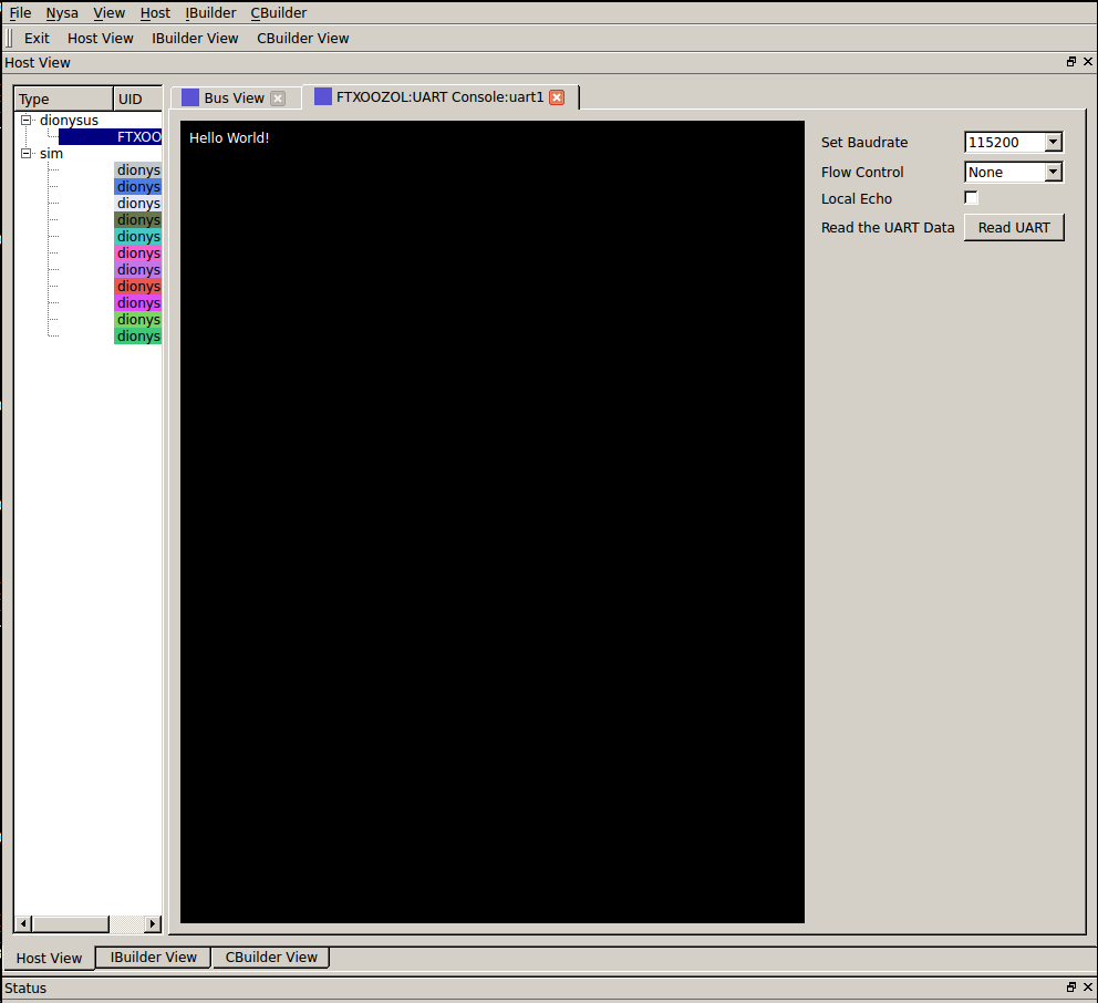
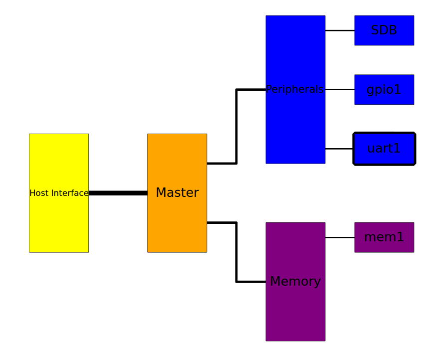
Visualize the FPGA image using Nysa GUI
If you attach a loopback wire like the following
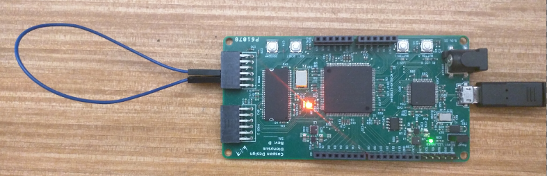
Using the nysa GUI we can use the UART plugin to demonstrate the UART